
For my graduation I designed a loadbearing structure using the filament winding composite forming technique. As a case, the pillar of a small pedestrian bridge was chosen for it had limited programmatic constraints but still should exhibit a high aesthetic value while maintaining a load bearing function.
The process consisted of a thorough literature research into the technical possibility within filament winding and the material properties. Through rapid production of prototypes the design fundamentals were determined and multiple shapes were investigated. The project went on with testing a basic shape by making use of a hand crafted winding configuration, the fibre glass in polyester matrix composite and a compressional test to validate the structural behavior hypothesis and loadbearing capacity. To conclude a 1 to 2 mock-up was made the express the aesthetic potential.

The 1:2 model had a light inserted in the connection with the bridgedeck

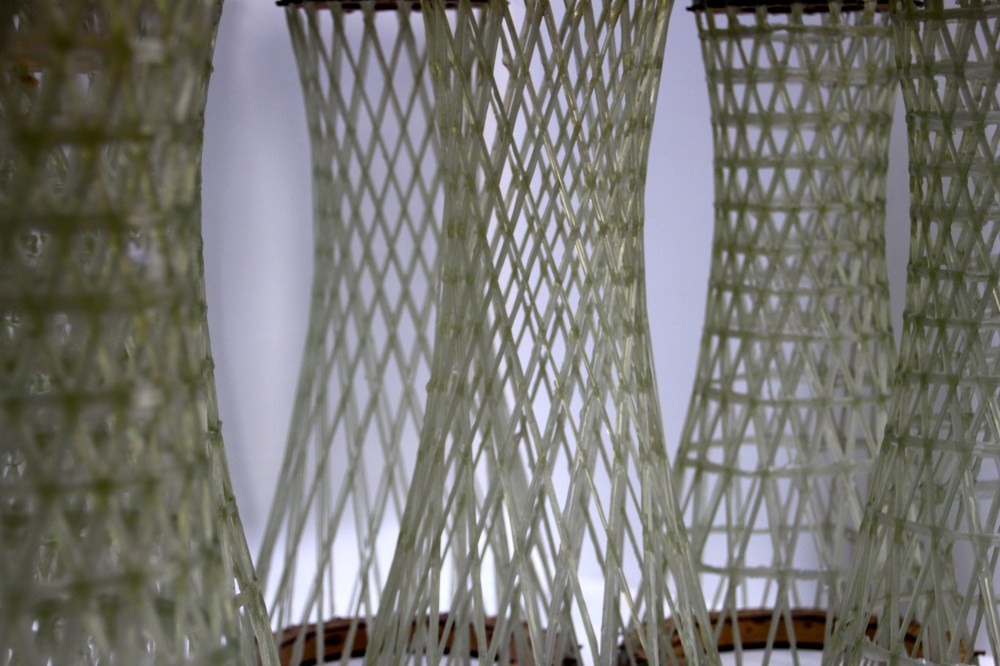
Close up of the ‘surface’ of the 1:2 model
During the process I wanted to deal with three aspects that gradually evolved to a rather specific ‘pillar for a pedestrian bridge’.
The first aspect is the lack of knowledge and hence limited use of structural composites in the building practice. Composites (fibre reinforced polymers) are complex materials that allow for a combination of specific properties and freedom of form. The counter side of this complexity is that the material is often optimized for its structural, chemical or deformational behaviour whilst the aesthetics is given little importance. In my opinion, the diversity of production techniques, which differ from most traditional techniques, allow for interesting structures deriving their aesthetical value through expressing its manufacturing technique. Especially with the advances in computer aided structural analysis the availability of complex optimized structures is drastically increasing within the field of architecture. Architectural faculties around the world are currently investigating the possibilities of aesthetic FRP structures, with ICD Stuttgart being my personal favourite and an essential reference during my graduation project.
Secondly, I have dealt with the aspect of the increased availability of production techniques through the development of user friendly and multiuse equipment and software that allow for the reinterpretation of existing production techniques. To give an example, a syntax can be made with Rhinoceros and Grasshopper for different types of 3D printers, robotic arms, milling machines and winding configurations. Furthermore, a robotic arm can be used to 3D print, mill, wirecut and wind. There are now a multitude of ways to create the same object. However, looking at it closely, each technique has some specific features which can be hidden or removed with post processing, but could also be used as a design aspect. To end the graduation project with a product I chose to start with an existing process and investigate the possibilities within architecture.
After the Buckylab studio in the first year of the master I realised how little we students knew about production techniques, materials and detailing and how much fun and valuable it is to actually build full scale and functional mockups. Not being able to substantiate the structural behaviour during earlier projects doing some real testing made it the third aspect I wanted to deal with.
Filament winding is a technique where a resin-impregnated bundle of continues fibres is wound onto a mould. Due to intersections in the winding path a structure is created. It is currently used for low and high-tech products such as tubing for corrosive liquids and gasses, drive shafts, pressure vessels and rocket fuselages. After its invention in the 1940’s it has been developed to one of the most automated and cheapest composite manufacturing technique whilst being able to achieve the highest possible fibre volume fraction. The technique has some drawback, such as the rather rough outer surface, as the mould is on the inside, and the fact that making a re-entrant shape isn’t a possibility due to the tension on the fibres.
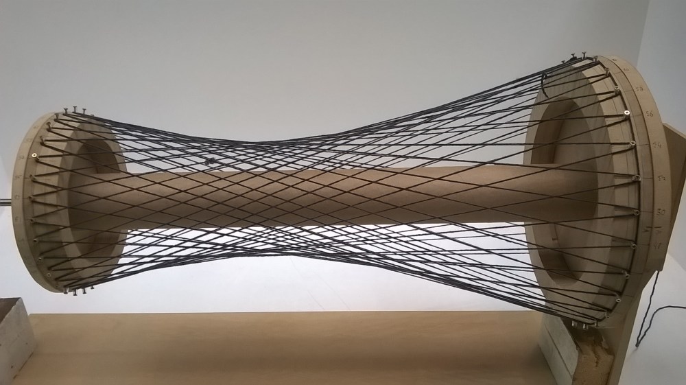
After I decided to use filament winding, an extensive literature study was made to become familiar with fibre reinforced polymers, a quite unknown material for most architecture students. During the reading a small winding configuration was made using MDF sheets and a threaded steel rod. In this winding bench wooden mould elements were placed to compress a tube to create an open core mould in which acrylic fibres are tensioned. This setup allowed the mimicking of the winding process to quickly investigate shapes and parameters. Moreover, the models were used to validate the Grasshopper script. The biggest advantage of physical model making was that it was quicker than altering the Grasshopper script. Small winding mistakes were made, which turned out to be essential in understanding the process. In an earlier stage of the process I developed a variety of models and principles based on the coreless filament winding technique. During this phase the idea of a pillar was deliberately suppressed to keep the options of using it as a beam, roof elements, cut out sections, including climatological features or using it for scaffolding for another material open. Ultimately, the plausibility or each concept would be determined by the strength of the connection of the intersecting layers of winding bundles. To substantiate the plausibility of wound composites in architecture this aspect was the crux of the research.
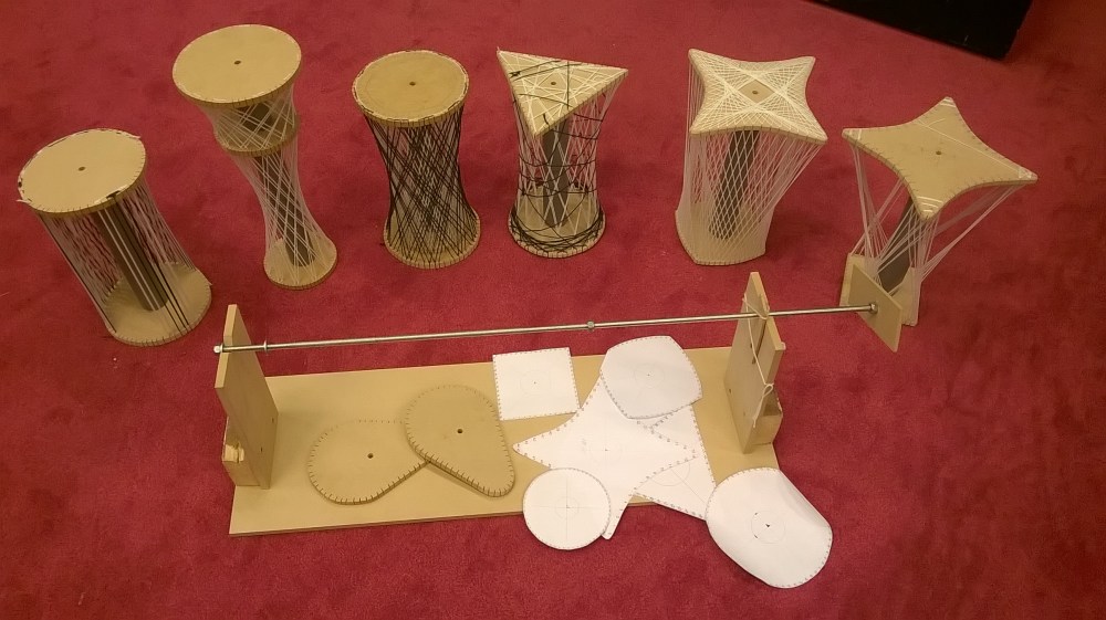
To simplify the assignment the decision of going for a hyperboloid grid was made. The rotational shape would reduce the complexity which enabled me to focus on the research of the essential aspects of a wound loadbearing structure. The shape is determined by just four parameters: the dimension of the moulds, the distance between the moulds, the amount of connection points and finally the shift in connection points the bundle makes when traveling between the two moulds.
The structural behaviour of the pillar raised some questions, which could not be answered conclusively by various tutors. The first was the behaviour of the hyperbolic shaped grid when loaded in compression: Would it act as a statically indeterminate net of beams or as a hyperbolic surface comparable with a concrete cooling tower? The second was the behaviour of a composite beam in compression, what would be the influence of the fibres? The final question was to what extend the intersections were strong enough to increase the overall strength of the pillar.
Because of these uncertainties in behaviour two design proposals were made. The first proposal (type A) only had the bundle crossing between the two moulds. The second (type B) had interwoven circular reinforcements at each level of intersections forming an iso-grid. Due to the tension on the fibres when wound the polar bundles of both types are straight. Physical tests were needed to come to a decisive conclusion on the structural behaviour.
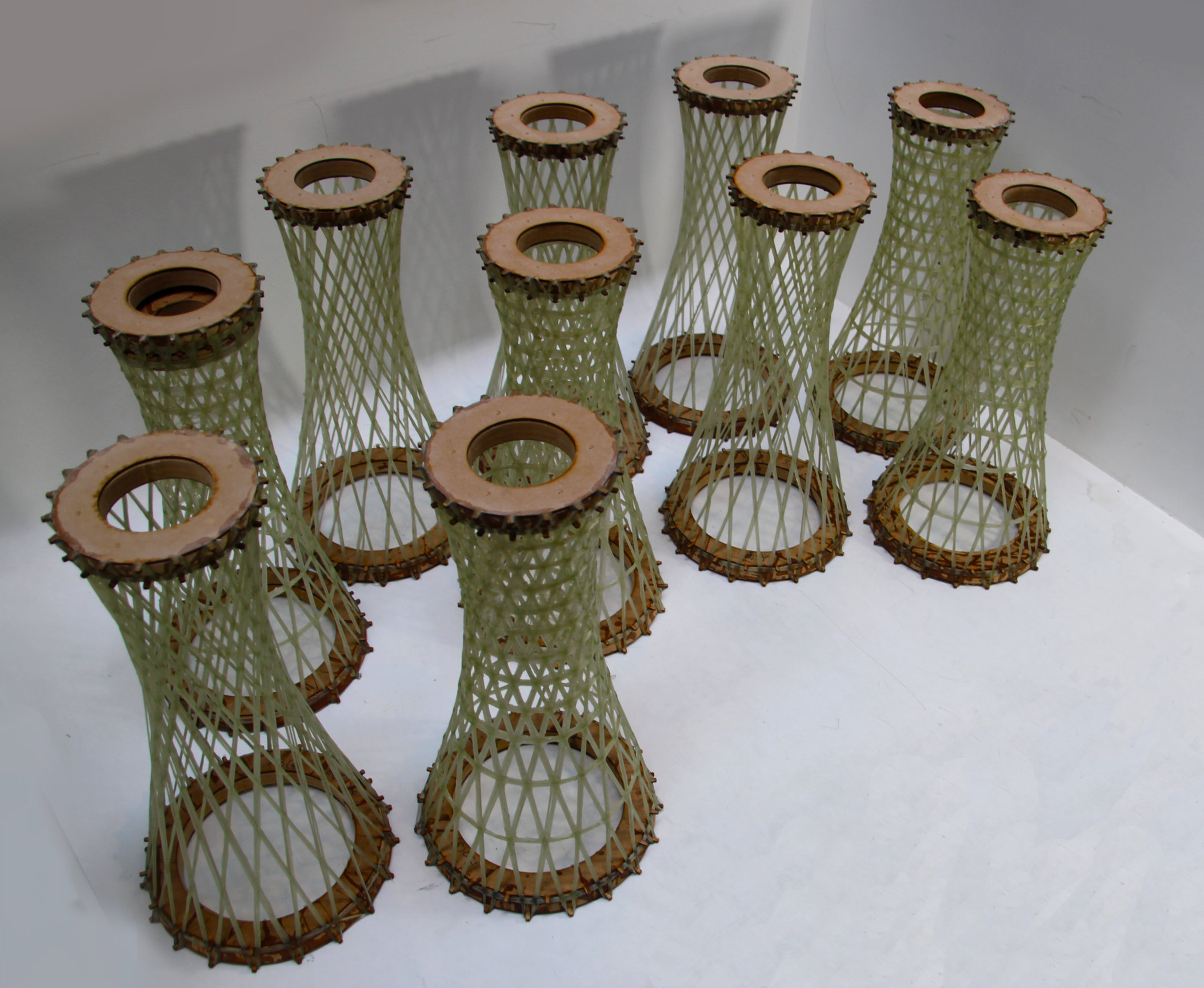
10 models were made on a 1:5 scale for the compression tests
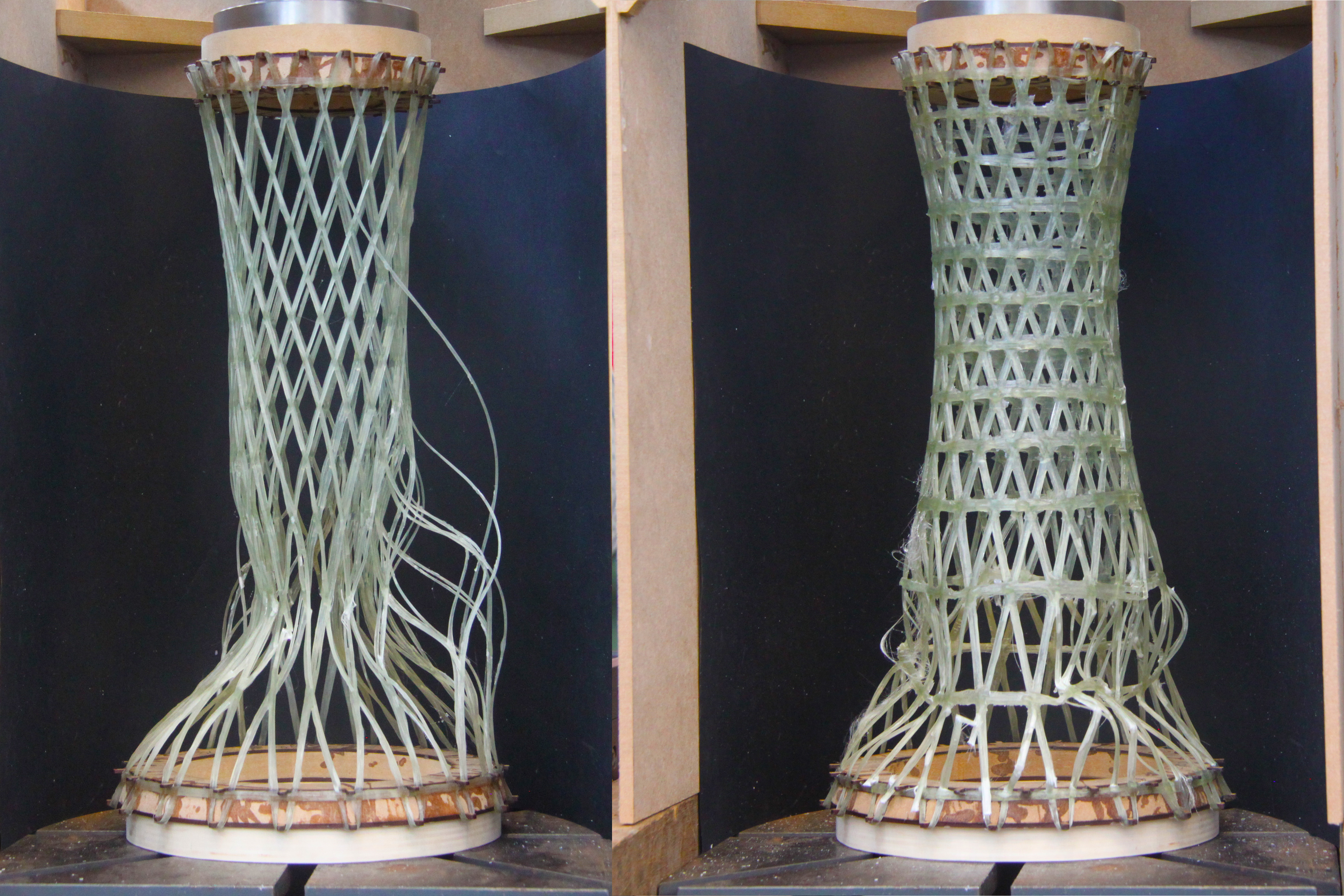
The two types undergoing the compression test
Through manual and Karamba calculations certain geometry parameters of the hyperboloid such as the amount of connectors and the bundle thickness were determined. Buckling seemed to be the primary cause of failure. The two previously mentioned types were made in fivefold to reduce the influence of production flaws. By measuring the weight before and after the winding process the mass of the composite was determined. The length of the three layers of fibres was then measured from the digital model and multiplied by the weight of the fibre bundle per length (2,4 g/m). Though these basic measurements the fibre volume fraction and the theoretical elastic modulus were calculated. Type A had 305 g of composite material and type B contained a 410 g average and had a similar fibre volume fraction of 30 percent and height of 50 cm. In comparison with commercial grade composites, which contain 50 to 70 percent this was extremely low. Higher fibre content inherently creates higher elastic moduli and yield strength.
The test bench measures the force required to move a certain distance. Type A could withstand a maximum of approximately 5000 N while type B went up to 10500 N before buckling. This result of the 410 g column being able to bear a 1000 kg load, comparable to a small passenger car, was unexpected.
As mentioned earlier the project was to negotiate between aesthetics and loadbearing capacity. The first aesthetical feature to be discussed is the expression of its production technique. Looking closely at the intersections one can see that they are created by weaving layers of bundles. A second aesthetic feature is the hyperboloid shape, which has a clear effect on the porosity of the skin. It becomes gradually denser towards the waist and the circular horizontal section creates visually denser edges when perceived from a distance in elevation. Finally, lights were added to create a playful shade in the dark.
Different gradients in elevation
In the end the project showed the possibility of winding aesthetical structural composites. I hope it will inspire students to shift from conventional materials and techniques to less common ones. I especially promote researching composite materials as it holds unexplored potential for architecture.

